Keyless Motorcycle Ignition System
December 2021
A system that allows a motorcycle's ignition to be enabled using a wearable NFC tag instead of a physical key while minimizing standby battery drain.
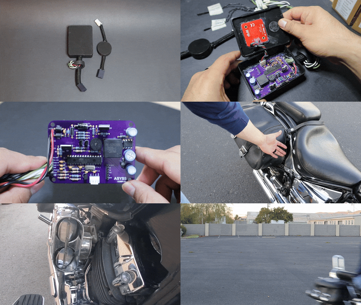
Overview
This project is a custom keyless ignition system that uses an NFC ring to enable a motorcycle’s ignition while keeping the original keyed ignition available as a fallback.
One of the main design goals was minimizing standby battery drain. Instead of leaving the NFC reader powered continuously, the system remains normally unpowered while the motorcycle is off. Pressing the brake pedal momentarily powers the controller, which then checks the NFC tag and, if authorized, keeps the system on and enables the ignition.
The project involved circuit and PCB design, embedded firmware, automotive electrical protection, CAD, 3D printing, wiring, and full vehicle integration.
Watch the Complete Project Walkthrough
This is a detailed video covering the system architecture, circuit design, firmware, fabrication, testing, and motorcycle installation:
You can download the full documentation file here
The source code is available on GitHub
System Architecture
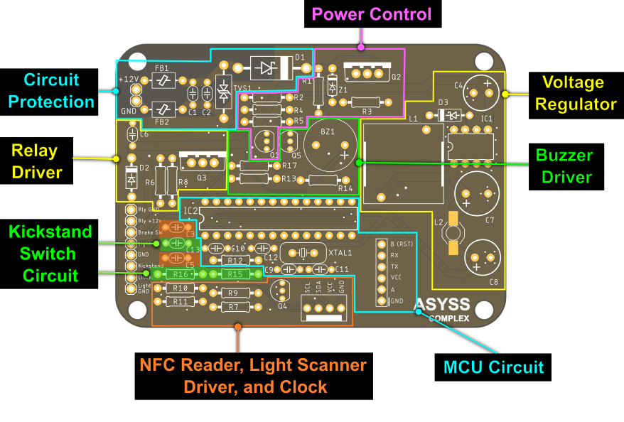
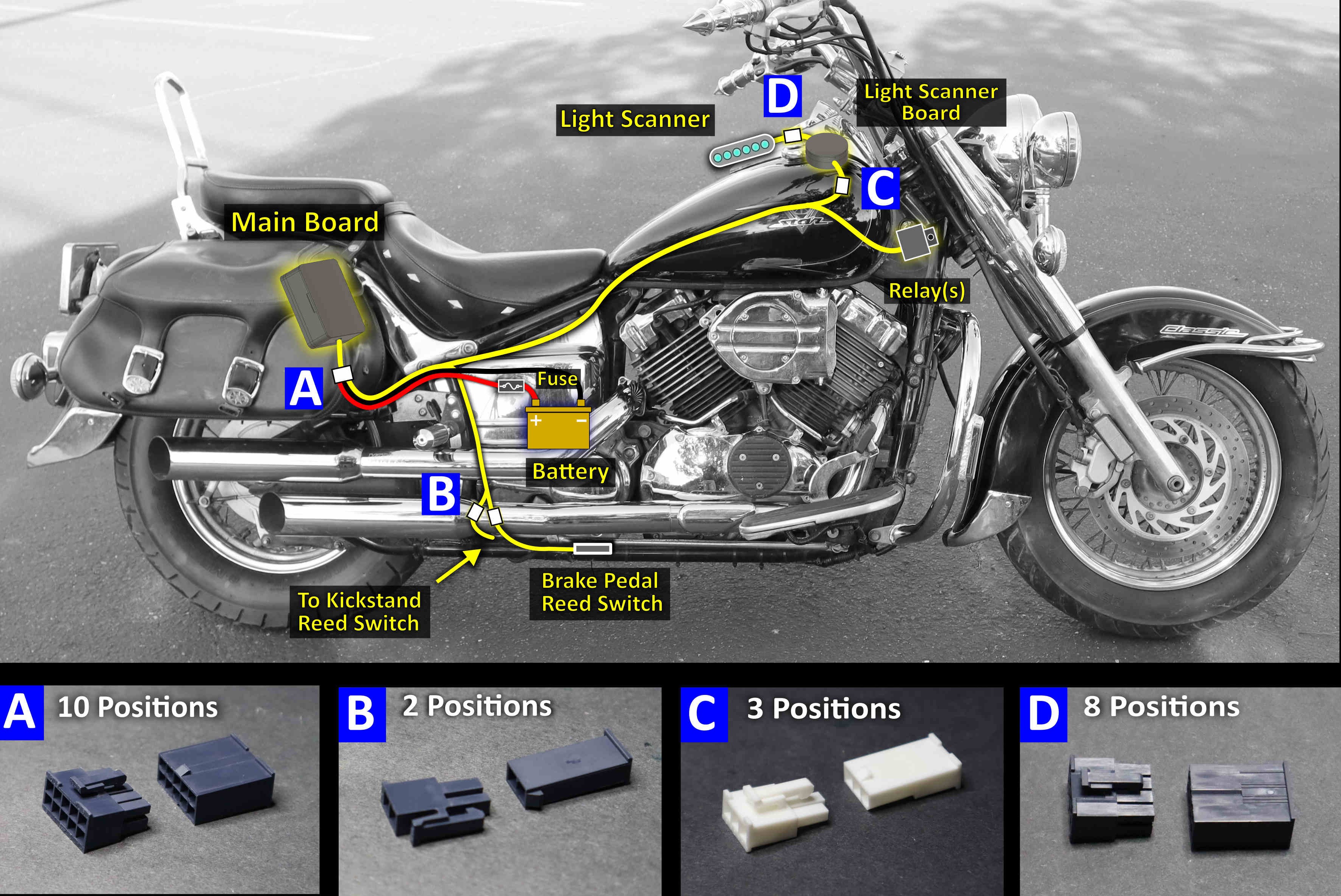
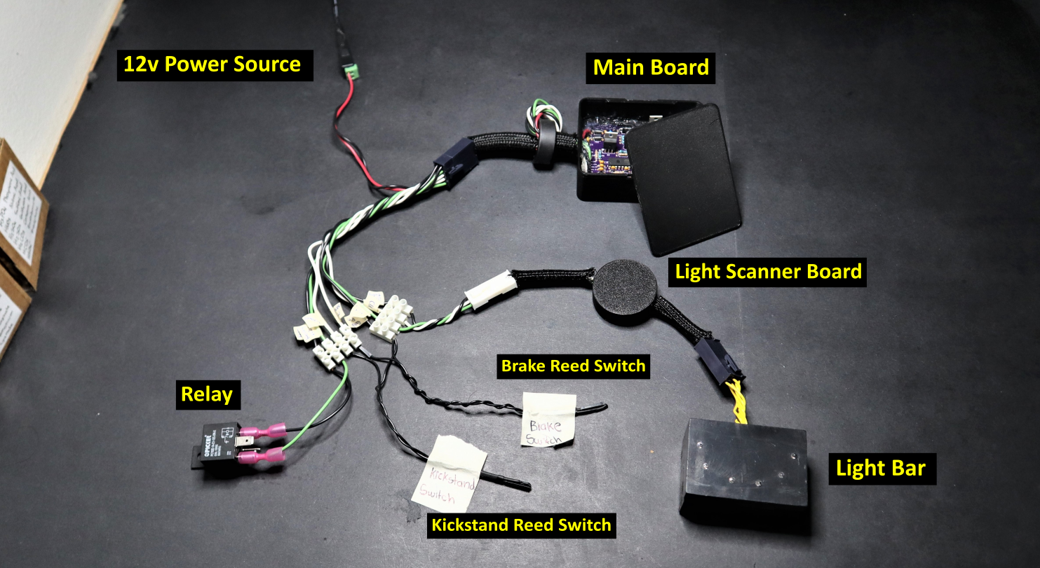
The system is centered around a main control board built around an ATmega328P microcontroller. Pressing the brake pedal momentarily powers the controller, allowing it to read the NFC tag. If the tag is authorized, the controller keeps the system powered and activates the relay that enables the motorcycle's ignition circuit.
Two reed switches provide the main external inputs. The brake pedal switch initiates the startup sequence, while the kickstand switch is used to place the controller into a low power state while the motorcycle is running and wake it again when the kickstand is lowered.
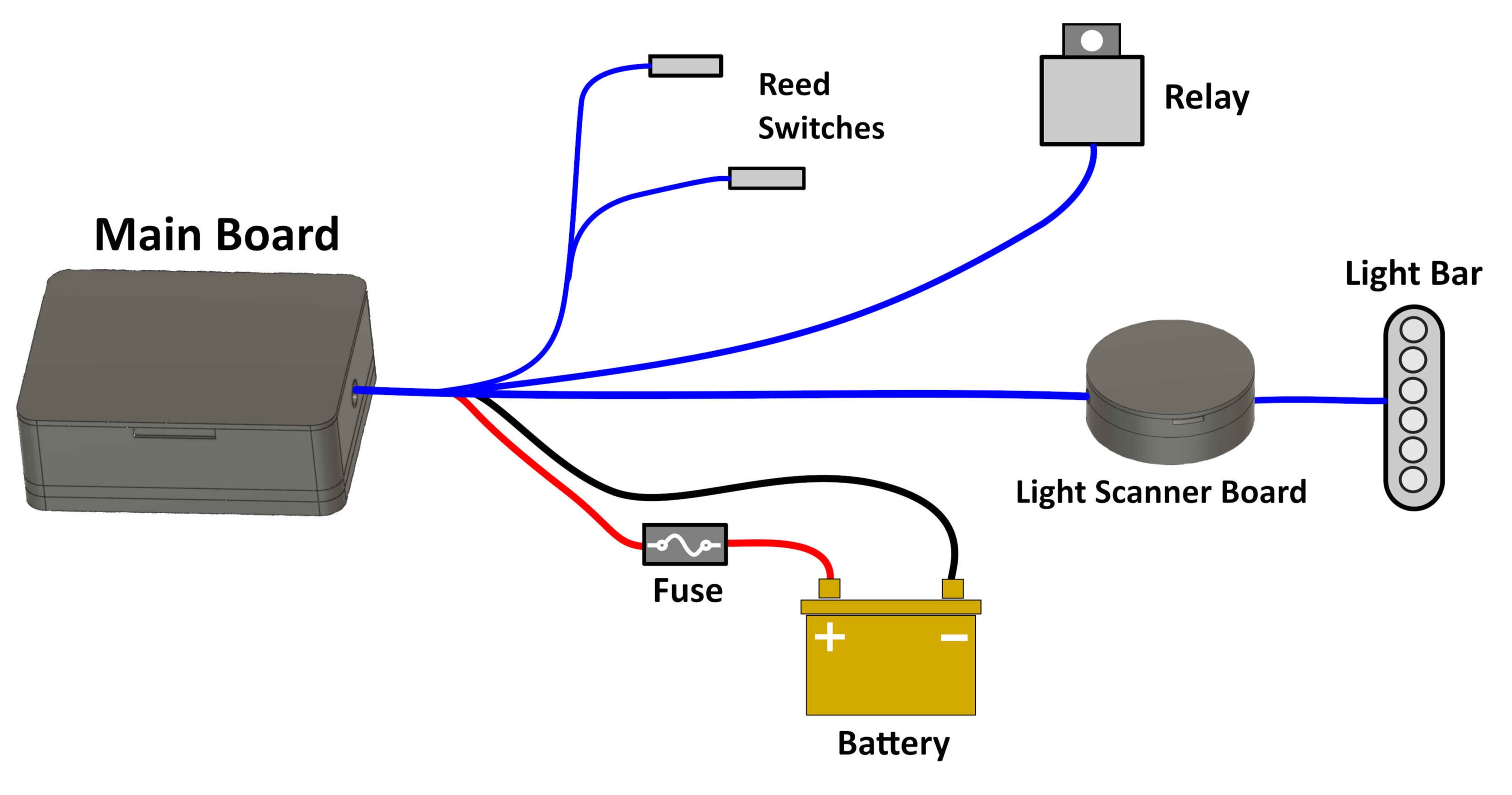
A separate light scanner board provides visual system feedback through an LED light bar. This module is not required for the ignition system to operate and was designed as an independent auxiliary board.

The system was designed as a set of separate functional modules rather than a single assembly. This made the ignition controller easier to test on the bench, simplified installation on the motorcycle, and allowed extra features such as the light scanner to be removed or modified without affecting the core ignition system.
Electrical Design
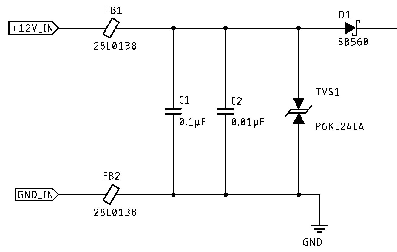
Because the system is connected directly to the motorcycle electrical system, the main board was designed to tolerate electrical noise, voltage spikes, and other transients. The power input includes a fuse, ferrite beads, decoupling capacitors, reverse-polarity protection, and a bidirectional TVS diode to help protect the electronics from high-voltage events. Relay outputs also include flyback suppression to reduce voltage spikes generated by the relay coils.
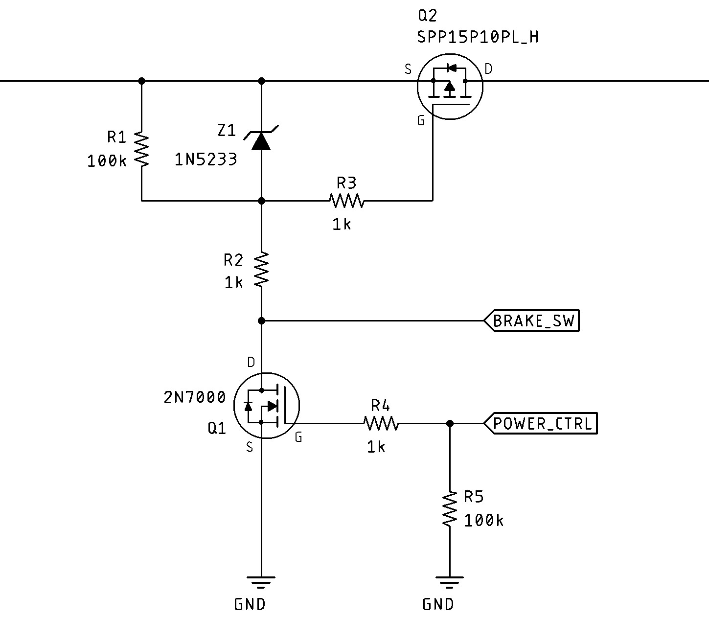
A major part of the circuit is the power-control stage. A P-channel MOSFET acts as the main high-side switch for the system. Pressing the brake pedal closes the reed switch and momentarily turns this MOSFET on. Once the ATmega328P starts, it drives a second N-channel MOSFET that keeps the main switch on after the brake pedal is released. This allows the firmware to completely shut down the board when the system is no longer needed.
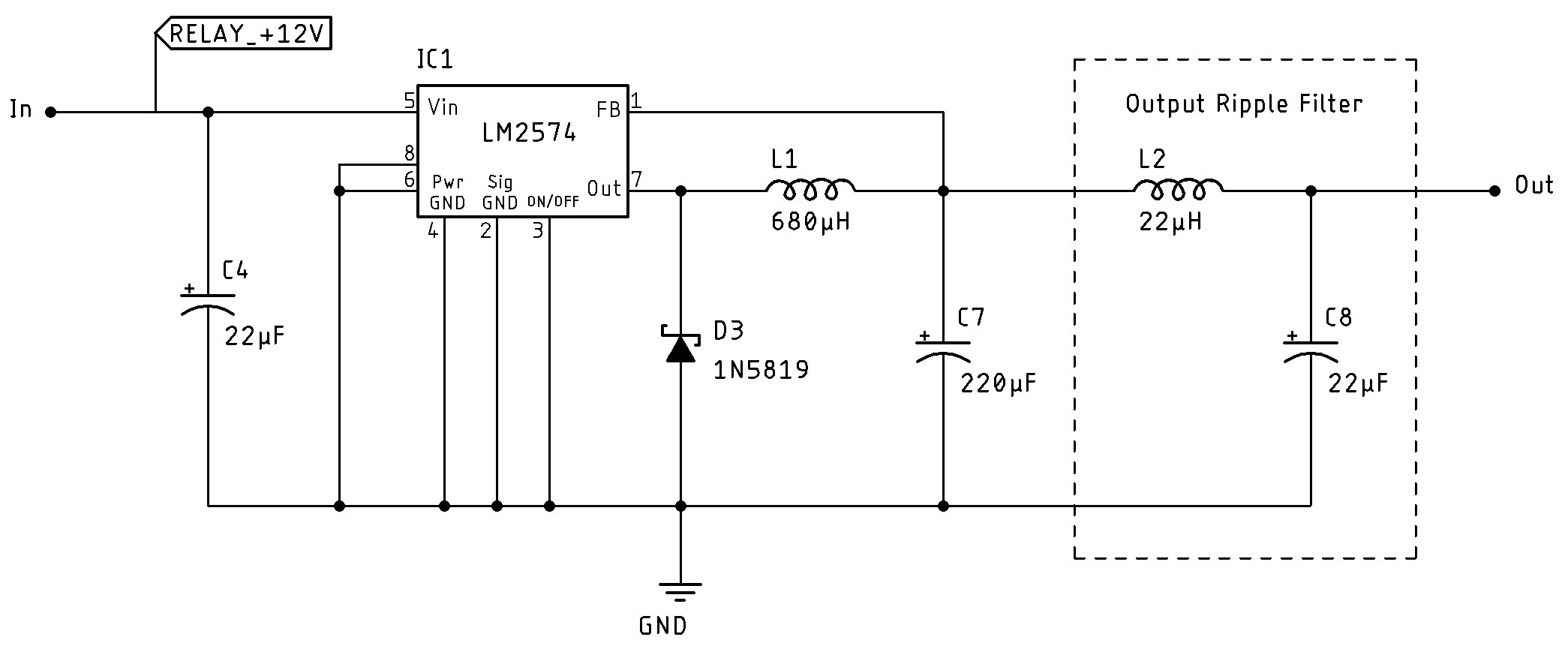
The 5 V rail is generated using an LM2574 switching regulator. I originally considered a linear regulator, but during prototyping it became inefficient and noticeably hot even at relatively low current. The switching regulator greatly reduced the power loss, although it introduced more switching noise, so an LC filter was added to clean up the output before powering the controller and peripheral electronics.
Firmware and Control
The firmware is organized around five main operating modes: Disarmed, Armed, Save/Delete Tag, Erase Memory, and Sleep Mode. These modes control how the system responds to NFC tags, manages stored credentials, and transitions between the motorcycle being off, enabled, or running.
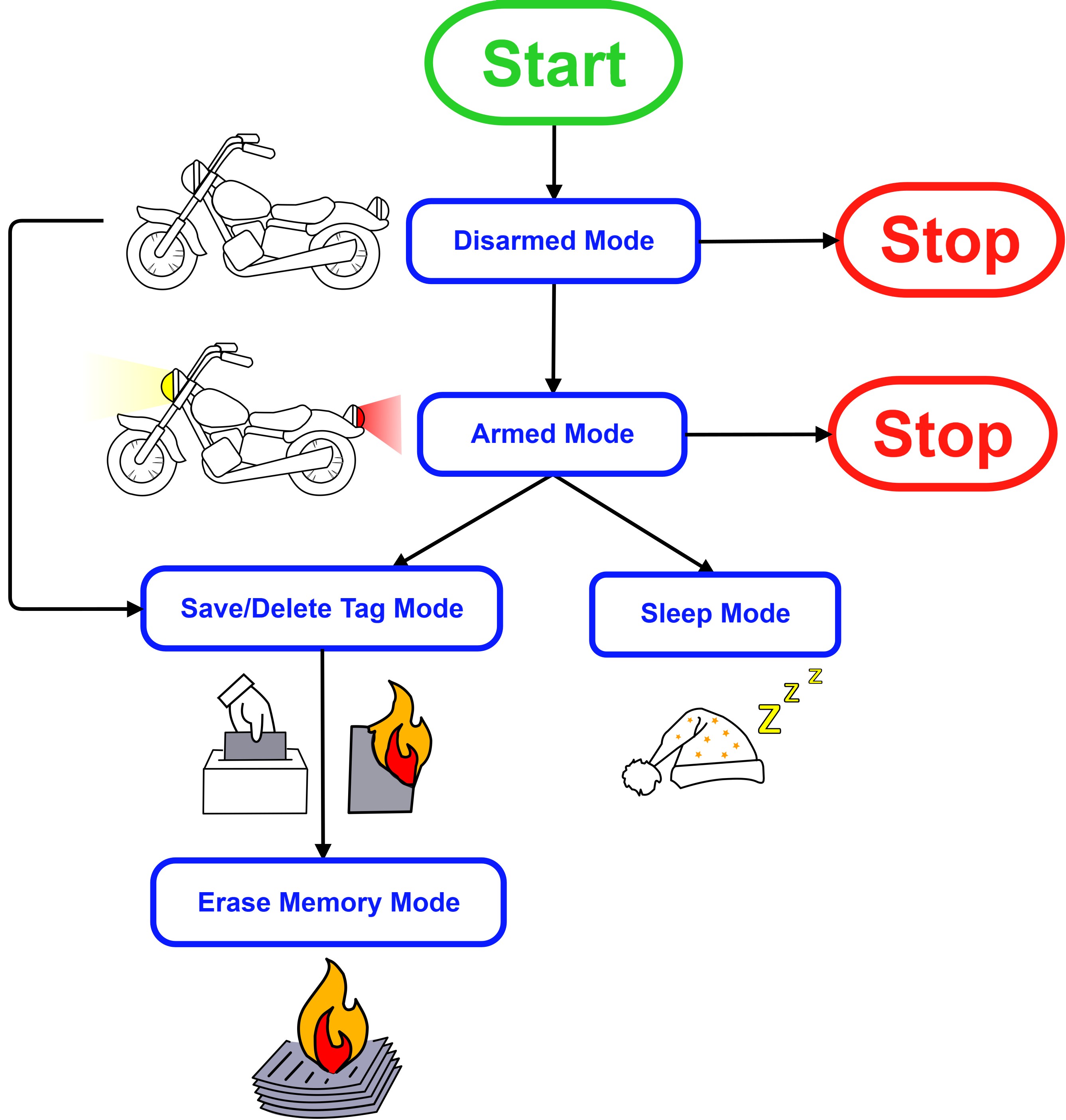
In normal operation, pressing the brake pedal powers the controller and places the system in the Disarmed state. The NFC reader then checks the scanned tag against the credentials stored in EEPROM. If the tag is authorized, the system enters the Armed state and enables the ignition relay interface. Scanning the authorized tag again shuts the system down.
NFC credentials are stored in the ATmega328P's internal EEPROM so they are retained when the motorcycle is powered off. Each entry uses eight bytes: one byte indicates whether the slot contains a valid credential, followed by the seven-byte NFC UID. With 1024 bytes of EEPROM available, the system can store up to 128 tags.
The additional status byte also simplifies searching the EEPROM. The firmware can check the beginning of each eight-byte slot to determine whether a tag is stored there before reading and comparing the seven-byte UID.
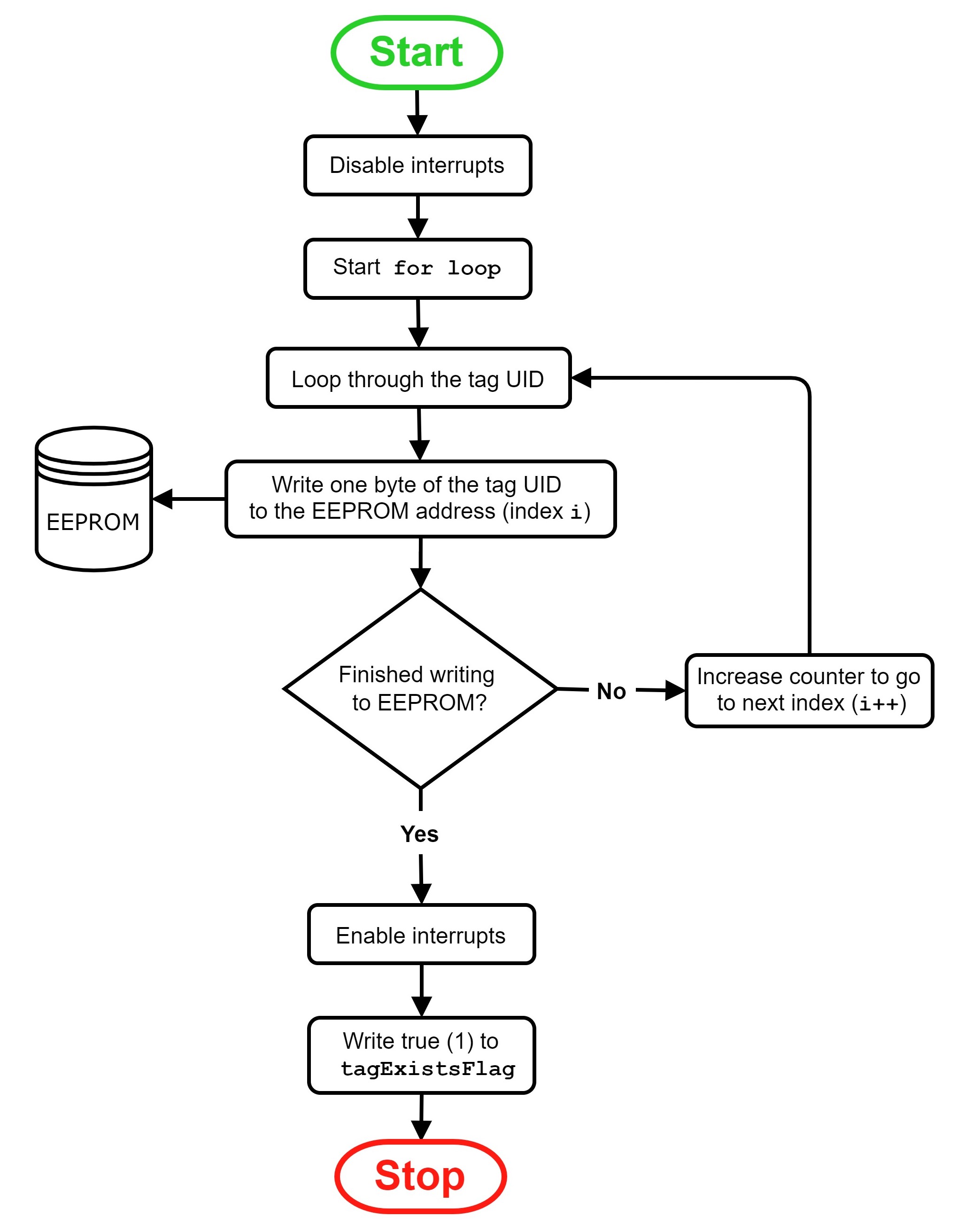
A master tag provides access to the Save/Delete Tag and Erase Memory modes, allowing credentials to be added or removed without reprogramming the microcontroller.
The kickstand input is also used for power management. While the motorcycle is running, raising the kickstand places the ATmega328P into its Power-down sleep mode and disables unnecessary peripherals such as the NFC reader and status lights. Lowering the kickstand generates an interrupt that wakes the controller so the system can respond again.
PCB, Packaging, and Vehicle Integration
The main control board was laid out by separating the circuit into functional areas for power input and protection, power control, voltage regulation, the microcontroller, and external interfaces. Components such as decoupling capacitors and the clock circuit were placed close to the devices they support, while ground pours were used throughout the board.
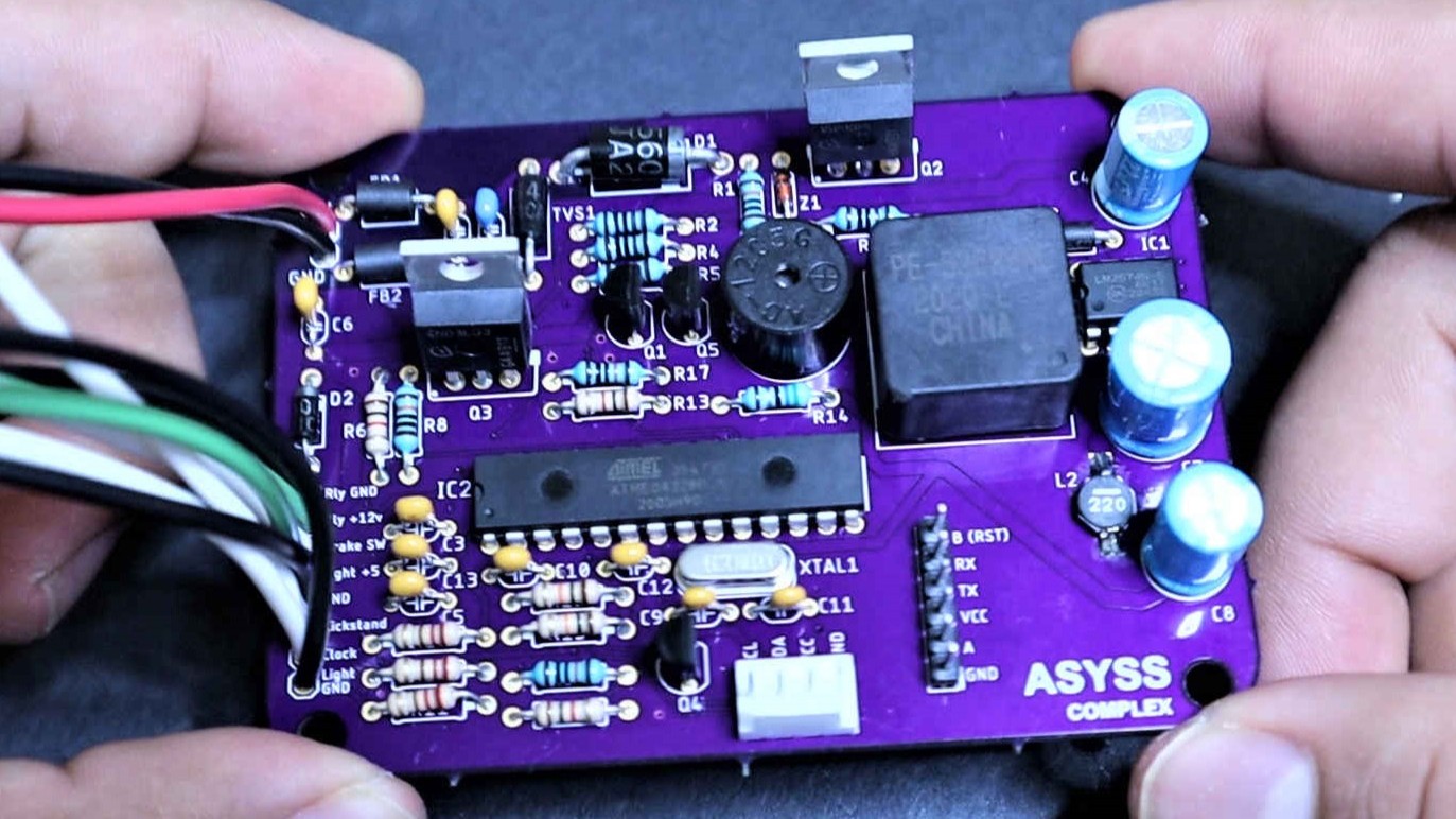
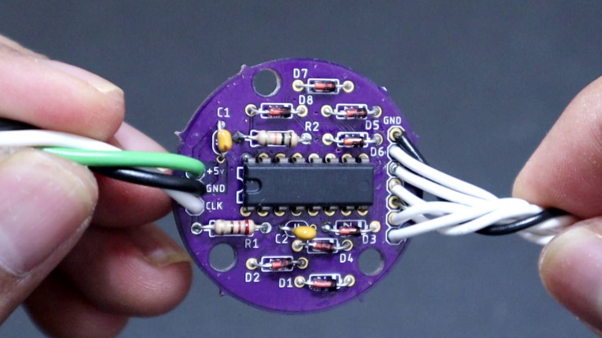
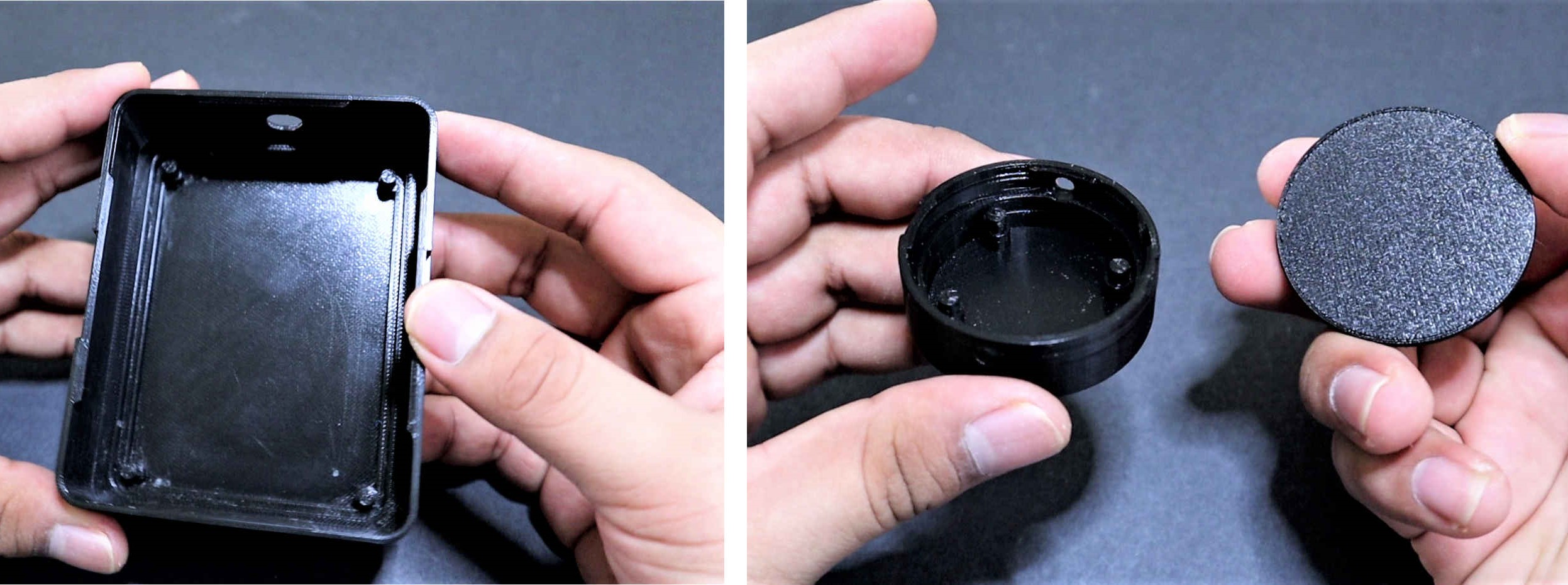
The controller and auxiliary boards were installed in custom enclosures designed in Fusion 360 and 3D printed. The enclosures use snap-fit covers instead of screws, and several dimensions were adjusted between prints to improve the fit of the PCBs and covers.
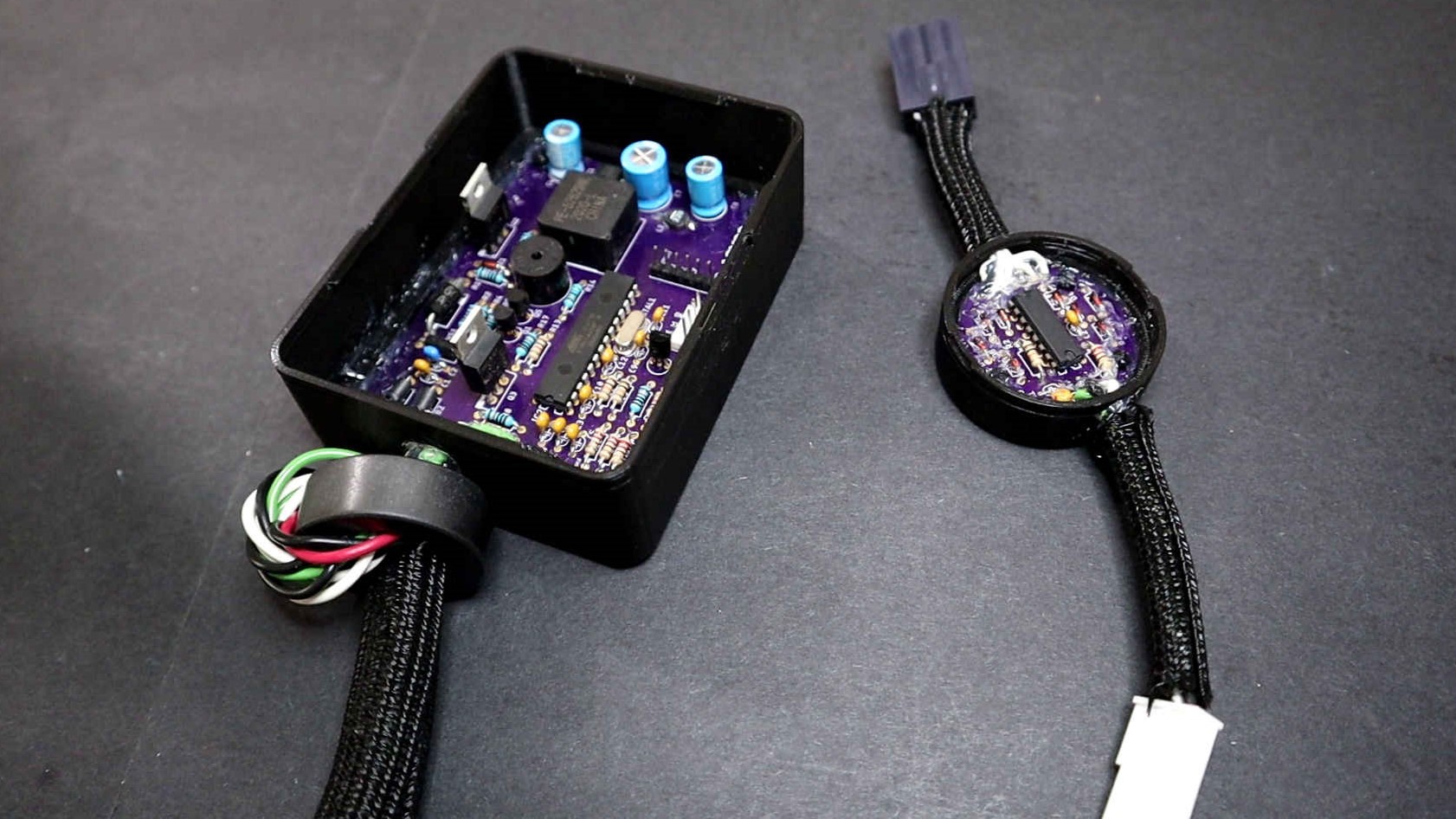
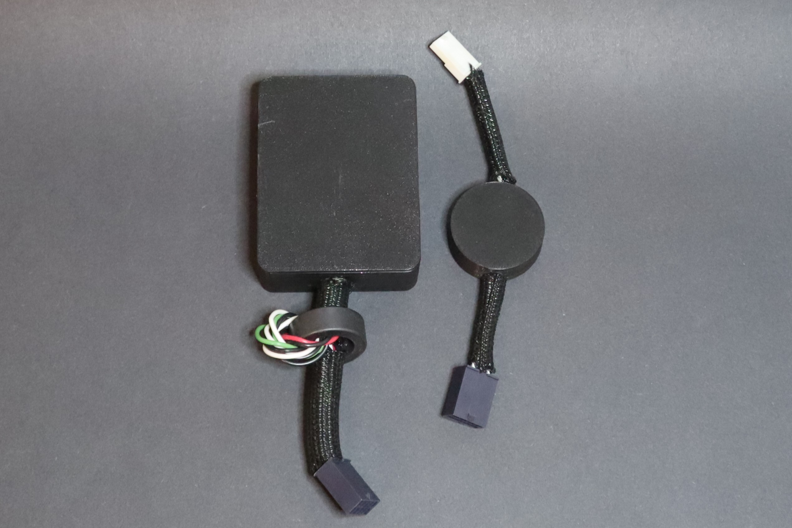
The wiring was also designed to be modular. Molex connectors were used between the main controller, NFC reader, reed switches, relay interface, and light scanner so individual parts could be disconnected for testing or replacement without removing the complete system.
Before installing the system on the motorcycle, the complete hardware was assembled on the bench using a 12 V power supply. This allowed the controller, NFC reader, reed switches, relay interface, and light scanner to be tested together and made troubleshooting much easier before working with the motorcycle wiring.
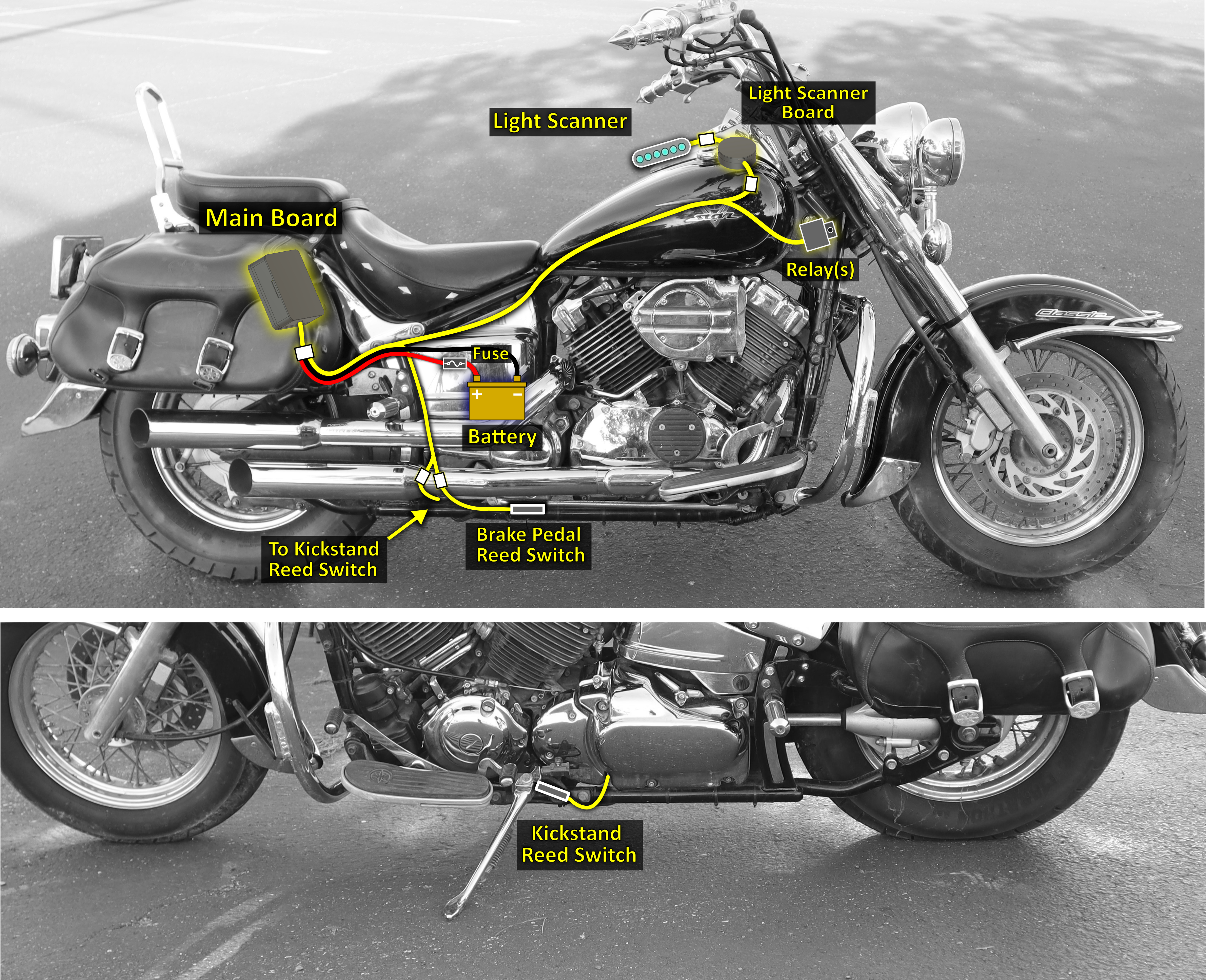
During installation, the original ignition switch was kept operational as a backup. The keyless system was connected through the relay interface to bypass the required ignition circuits when an authorized NFC tag was used, without removing the original keyed ignition.
Results
The completed system was installed on the motorcycle and used regularly for several months. The NFC ring could be used to enable and disable the ignition as intended, while the original keyed ignition remained available as a backup.
On my motorcycle, the NFC reader was installed inside the main board enclosure in the saddlebag, which provides easy access when scanning the ring.

The power control design also achieved the main goal of avoiding continuous battery drain while the motorcycle was off. The controller and NFC reader remain unpowered until the brake pedal is pressed, and the firmware can shut the system back down when it is no longer needed.
The final installation combined the custom controller, NFC reader, reed-switch inputs, relay(s), light scanner, wiring, and 3D printed enclosures into a complete system that could be serviced or modified as separate modules.